
1G Fan Control
Enable Clone2 ECU Radiator Fan Control
The 1G (1991-1993 ) US versions of the 3000GT and Stealth had combination A/C Compressor Lock Controller and thermo-sensor controlled radiator fans while the 1994 and up US versions of the 3000GT and Stealth had ECU controlled radiator fans. In order to swap to ECU controlled fans, you must both disable the A/C Compressor Lock Controller Fan LO over-ride and change the Fan LO / Fan HI relay activation from the thermo-switch to the ECU.
Fotunately, wiring in the fan relays is actually easier than it sounds. All of my Plug n’ Play harness have two color coded wires, Light Blue (Fan LO) and Purple (Fan HI), that are heat shrink capped and ready to use.
If you order the 8 ft Fan Hi / Lo Relay Wiring Option, you will also receive approximately 8 ft of TXL wire wrapped in 1/4 in F6 Flexible, Semi-Rigid Wrappable Split Braided Wiring Loom (Temperature rating: -103F to 257F; Melts at 482F), along with two butt connectors for under dash use and two PermaSeal heat-shrinkable butt connectors for under-hood use.
 Step 1
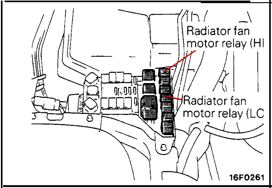
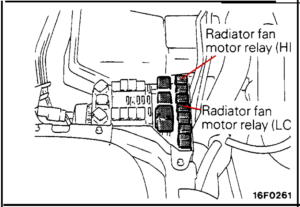
Locate the under-hood relay box near the passenger side headlamp and locate the two fan relays. Remove both relays while working on this system. DO NOT DISCARD.
[icon name=”icon-info-sign”]NOTE: It is important to NOT wire this into the radiator fan relays directly as doing so will disable the Condensor Fan HI motor when the Fan HI relay comes on.
 Step 2
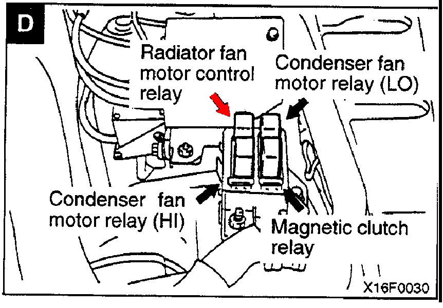
Locate the air conditioning relay box near the drivers side front strut tower. If you have cruise control, this will sit directly in front of the cruise control cable junction box. Remove the “Radiator Fan Motor Control Relay” and discard. This will disable the manual A/C Compressor Lock Controller Fan LO over-ride giving full fan control to the Clone ECU. DO NOT REPLACE THIS RELAY.
 Step 3
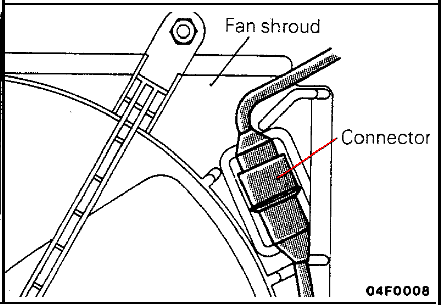
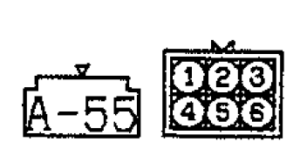
Locate the fan control plug (A-55) located on the passenger side top corner of the radiator attached to the fan shroud. This plug will have six wires.
- Pin 1 – Black – Ground
- Pin 2 – Red with Black Stripe – +12 v to Fan Motor
- Pin 3 – Blue with Black Strip – Fan LO Relay Activation
- Pin 4 – Blue with Yellow Strip – Fan LO Relay to Fan Resistor
- Pin 5 – Blue with Green Strip – Fan Motor to Fan Relays
- Pin 6 – Green with Black Strip – Fan HI Relay Activation

Step 4
Locate pin 3 and the Blue with Black Strip wire. On the VEHICLE side of the fan plug, cut this wire approximately 2″ from the plug. Using the supplied PermaSeal butt connector, connect the wire going into the vehicle harness (NOT the wire going back to the plug) to the supplied Light Blue wire.
Step 5
Locate pin 6 and the Green with Black Strip wire. On the VEHICLE side of the fan plug, cut this wire approximately 2″ from the plug. Using the supplied PermaSeal butt connector, connect the wire going into the vehicle harness (NOT the wire going back to the plug) to the supplied Purple wire.
Step 6
Using a heat-gun or other non-flammable heat source, shrink the PermaSeal connectors. Tape off the cut wires going back to the fan plug. Route the remaining wire along the passenger side of the car and into the passenger compartment, keeping it away from any exhaust pipes. Continue routing the wires to where you have your Clone2 ECU installed. Be careful to avoid all pinch points and sharp metal edges so as to not cut the wires.
[icon name=”icon-info-sign”]NOTE: If you wish to test that you have this wired correctly, you can replace the relays, and by grounding the Light Blue wire the Fan should come on LO, and by grounding the Purple wire, the Fan should come on HI.
Step 7
Using the remaining butt connectors, match up the colors and connect the wires to the Plug n’ Play harness. Replace the Fan LO and Fan HI relays.