Idle
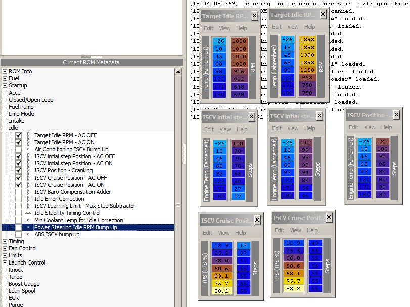
This was actually the most straight forward area of the disassembly. Too bad in Chrome V1 I had it all wrong…. Nearly all the tables I had listed in that XML didn’t do what I thought. There were various flags I didn’t understand at the time. Turns out the park/neutral switch was the trigger between each table set. With the P/N switch always being grounded on our cars (because of the MTX) only one set of tables were used and the target idle for the AC was just a single cell, not a whole RPM based 2D table.
In V2, I made a couple branch tweaks so the code never uses the duplicate tables and I tweaked the target idle tables to incorporate the AC function based off RPM.
Turns out, the ISC does quite a bit more than just handle idle. It’s got a fixed position for start-up and it changes for cruising as well (suspect it’s to help bring the RPMs down slower when you’re off the gas changing gears). The starter and idle switch differentiate between the various ISC tables. Best to make sure both these switches work when doing a flash ECU swap. I’ve labeled the flag bits in EVOScan.
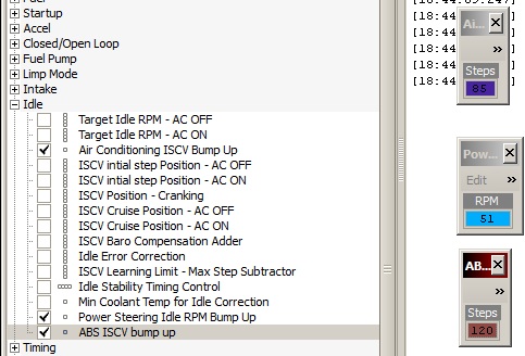
There are 3 other temporary ISC bump up conditions. There’s a minor bump up for when the AC is initialy turned on (which then tapers back to the AC ON conidtions), when the ABS is triggered and when you turn the steering wheel.
The last thing I want to go over is the idle timing stability control area of the code. The ISC will get the airflow in the right range for your desired idle RPM but it’s ignition timing which is used to keep the idle at the desired speed. You’ve probably noticed that at idle, your timing values are always inconsistent and constantly jumping around. This is why.
There are two variables in the ROM which the code references. One is the sensitivity variable and the second is a max timing adjustment limiting variable.
Not sure exactly what the sensitivity number translated to English means but I know that raising this value will increase the number of timing corrections per second and the timing limit is + or – 8 deg in the 99 ROM. This is how it’s calculated:
TimingCorrection = Sensitivity/64 * (TimingLimit / 500 * TargetIdleRPM – .256 * RPM)
This Timing Correction value is added/taken away directly from the base ignition map. The timing corrections are applied afterwards.
Now when you put the ECU into SAS mode, one of the things the code does is set the timing limit to 0 and fix the ignition timing to 5 deg so you can set the base idle with the BISS. This is one of the reasons why it’s important to set the idle with SAS mode and not play with the BISS while the idle timing stability controller is active. You’ll get inconsistent idle doing it that way.
Discussion Here: Disassembly: Idle
This page was posted on Tuesday, April 16th, 2013 at 11:47 pm by bfarnam and last modified on Friday, April 19th, 2013 at 11:34 pm by bfarnam


