
Intake
Try to let go of the notion that the stock MAF is some intelligent air counter and try to think of it more in the terms of any 5V sensor. There’s a voltage and a scaling (the ECU associates the input pulses to some amount of air). Granted it’s not a linear varying voltage signal like a wideband O2 sensor or a MAP sensor, but it’s still a 5V pulse signal sent to the ECU. The faster the pulses, the more air.
The MAF sensor can only read air volume. Dennis has a great explanation for how the mitsu MAFs work.
Originally Posted by DG
The Mitsu Karmann air flow sensor is a volume sensor – so you are right in saying “it’ll show the exact same pulses for 70deg air as it does for 110 deg air” because (assuming all other conditions are equal) the volume of flow is the same. What changes with the temperature change is the density, and with it, the mass.
So the Mitsu “MAF” must be temperature and baro pressure compensated in order to produce a mass value, which is what we want. And by no small coincidence, the sensor has a baro pressure and air temp sensor in the body of the “MAF”.
Hot wire sensors – like the GM sensor – use an entirely different measuring system (the amount of cooling on a heated wire) and these sensors measure air mass directly with no need to temperature or pressure compensate (at least on paper – I would not be surprised to find out that GM ECUs use some “fudge factors” to cover for where theory diverges from practice)
Knowing the volume doesn’t get you anywhere, since the number of air molecules in a given volume changes with temperature and pressure. If you know air volume, temperature and pressure though, you can get air mass. Air Mass can be used to determine the correct amount of fuel.
This is one of the reasons for the closed loop feature of the ECU. Even with all the tables used to calculate air mass, your final number is only as good as the base number. Even a completely stock, perfect condition car will have varying fuel trims depending on the weather outside. You’ll never ever have a perfect 0% trim under all weather conditions.
Originally Posted by DG
The trims are less about weather as they are about engine wear and general chaos (in the mathematical sense). Remember that the reasoning behind closed loop fuel control is emissions. The manufacturers were forced to go closed-loop-control by increasingly tighter emissions standards over increasingly longer periods of time. As engines wear, build up carbon, spark plugs get weaker, injectors clog etc the calibration changes (slightly) and your emissions change accordingly. Closed loop allows the ECU to compensate for these drifts away from the mechanical state of the engine as it was delivered from the factory.
Closed loop will also accomodate errors in your weather-related tables as well (and for tuners, your fuel tables) which is why I cheat like a bastard and run closed loop with a low lean-out authority and a high enrichen authority all the time (with a pair of wideband sensors), tweaking fuel tables to try and minimize the amount of O2 correction. The OEM, with a narrow band O2, can’t cheat like this except on cells where it is supposed to be 14.7:1 so the weather based corrections are probably very good (thus the reason why I want to duplicate them)
So how does the ECU calculate airflow? It starts with the MAF Size and the MAF Pulses. The larger the MAF size number, the more air the MAF can count (in the code, you must set this value according to the MAF you’re actually running)
AirCount = MAF Pulses Per RPM
MAF Hz = MAF Pulses Per Second = AirCount/RPM
Load is the term used for years as a number value to show how much air volume there is. More Load = More HP. So the object of the game is to get as much airflow in the motor as possible. 😉
Load quite simply is just Air_Count * MAF_Size / 65536. This is uncompensated Load (meaning Air Temp and Baro haven’t been applied yet).
Being able to read this number accurately is advantageous over the traditional boost gauge/butt dyno as you’re able to see if your airflow numbers go up with each mod performed. When you get to the point where you keep raising the boost, but airflow isn’t increasing, then you hit the limit of the efficiency of your turbos on your particular setup.
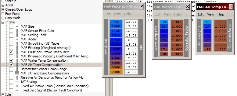
Caution! There’s a MAF Pulse Limitation in the code. This isn’t a physical limitation of the MAF itself, just an issue where the ECU will stop adding fuel past a certain PPS (Pulse per second) due to a 1 byte limitation in memory. Beyond this limitation, the ECU will stop adding fuel so be forewarned.
This limitation is 13.06 PPS or 319.7 grams of air/second (table is shown in the V2 xml). With a stock MAF, this is only about 450hp depending on which HP calculator you’re using. This is coincidentally is about where the stock 3/S MAF also seems to run out of resolution. Thought that was interesting. Obviously the car is capable of making more power as people have been doing so for years by fooling the ECU into seeing less air with a piggyback.
I’m not sure what this limitation is with an EVO MAF yet. The EVO MAF won’t pulse as often for the same airflow as the stock 3/S MAF and I need more data to make an educated guess. Wouldn’t be surprised if the limitation is double the stock 3/S MAF. If the demand requires I come up with a way around this limitation, I can, but for now, I’m not going to worry about it till we start seeing more big builds with the Flash ECU.
AirFlowMAX = MAFLimit * AirTempComp * WaterTempComp
*Note: These 2 comp tables are only used for calculating MAX airflow NOT engine load. Also note they are just set to 1 so they are disabled anyway.
So that’s airflow. Next the ECU calculates a MAF Correction value for the injectors during the IPW calculation. It does this using the MAF Scaling, Adder and VE tables. The MAF Smoothing table is just a way to measure the engines Volumetric Efficiency (VE).
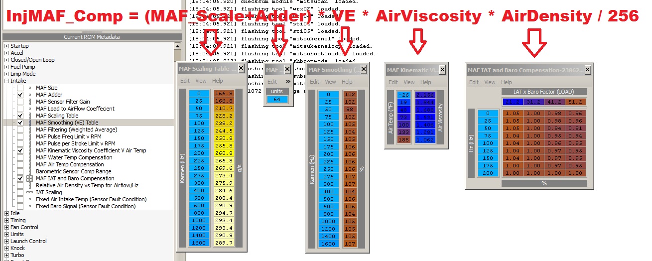
Changes to MAF Smoothing (VE) Table will produce large results relative to the value in the Scaling Table. So if you need to adjust the amount of fuel based on airflow, adjust the values in the VE table. It’s kinda like an SAFC in a way only you’re going off the actual MAF values instead of RPM. The higher the number in the VE table, the more fuel the ECU will use. Lower values = Less fuel.
It’s important to note that changes to your intake, innercoolers exhaust, head work, turbos… All this changes your particular engines VE and the MAF may not detect this change in airflow. This table is tuned for a 100% stock car. Something as simple as hard pre-turbo intake pipes can effect the readings from the MAF as more can sneak thru it without being detected.
When tuning cars, I don’t mess with the fuel injector size and latency values beyond setting up the values for whatever injectors is being used. Most people also tend to want to play with the fuel table too much during initial tuning, but if you get your VE table setup just right, the AFR value you see in the fuel table is what you’ll get on the wideband.
The fuel trims are handy for tuning this table. If your trims are increasing, add more to the VE table in that range to bring them back to 0. If your trims are negative, lower the numbers.
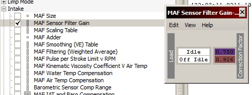
Something interesting in the code is an idle correction factor during it’s airflow calc process. Since at idle vacuum is so great, it causes an anomaly with the idle AFR in that the ECU will think there’s a lot more air there than what’s actually flowing thru the MAF. This correction is based off the idle switch and it works to differentiate the low fuel trim between idle and just low speed driving.
When you install cams and vac is a lot less than stock, consider bringing up this idle correction factor a bit as it may cause too lean of an idle mixture (not that a lean idle is really is a bad thing).
Discussion Here: Disassembly: MAF tables and Air Flow Calculation
This page was posted on Tuesday, April 16th, 2013 at 11:40 pm by bfarnam and last modified on Friday, April 19th, 2013 at 11:33 pm by bfarnam